Interapid Movement — Elements, Mechanism, Fault Diagnosis
Elements, torque chain, preload definition, and diagnosis for minimum-necessary disassembly — Meyer's technique applied within a resale workflow
00 Governing principle and scope
This resolves the apparent tension between his method and this document. Under minimum-necessary disassembly, targeted diagnosis is not wasted effort — it is what determines how far to open a unit, and whether to open it at all. Meyer's warning still applies at full strength within its scope: once a teardown is underway, do not fight the instrument trying to pre-identify the fault; let it surface during methodical reassembly. And his full refurbishment remains the correct call whenever inspection reveals general contamination or wear — a targeted fix on a dirty movement fails his quality bar.
Where this document applies
- Depth-of-disassembly decision. The primary role. §05's fork and §06's localisation determine which region of the movement must be opened, and how far — before a screw is turned.
- Acceptance testing. The functions-as-new standard implies a measurement that confirms it. §03 and §06 Step 3 supply that: measuring force, spring rate, and reversal error, all taken on the assembled instrument.
- Triage before commitment. Whether a unit is worth the labour at all, or whether a donor is the better path — a resale question a committed-repair shop does not face.
Under the standing rule that hardware is the authority over literature, every claim carries a status marker. Regions of the movement not yet accessible are marked and left empty rather than inferred.
Photography in §01–§02 was taken from a disassembled horizontal model, simply because that is the unit that was open. Vertical-model photography — including the 312B-1V — is to be added when such a unit is next on the bench. Should any future observation reveal a genuine movement-level difference between variants, record it against its own specimen rather than merging it into the shared sections. Known variant differences are body-level only: dovetail count and contact point swivel range.
Verified observed on hardware Hypothesis reasoned, untested Unknown no source of truth
01 Elements
Crown gear Verified
A compound brass component carrying two distinct tooth sets on a single body:
- Peripheral set — fine teeth around the outer circumference. Meshes with the internal lever assembly. This is the movement's input.
- Face set — a smaller ring of radial teeth standing axially proud of the face, inboard near the hub. Drives the pinion. This is the output.
The crown form exists to turn drive through 90°, not to accommodate any inclination. The lever shares an axis with the crown gear and drives it through the peripheral teeth as a parallel-axis mesh; the axial face teeth then transfer motion into the pinion, which runs on the pointer axis perpendicular to it.
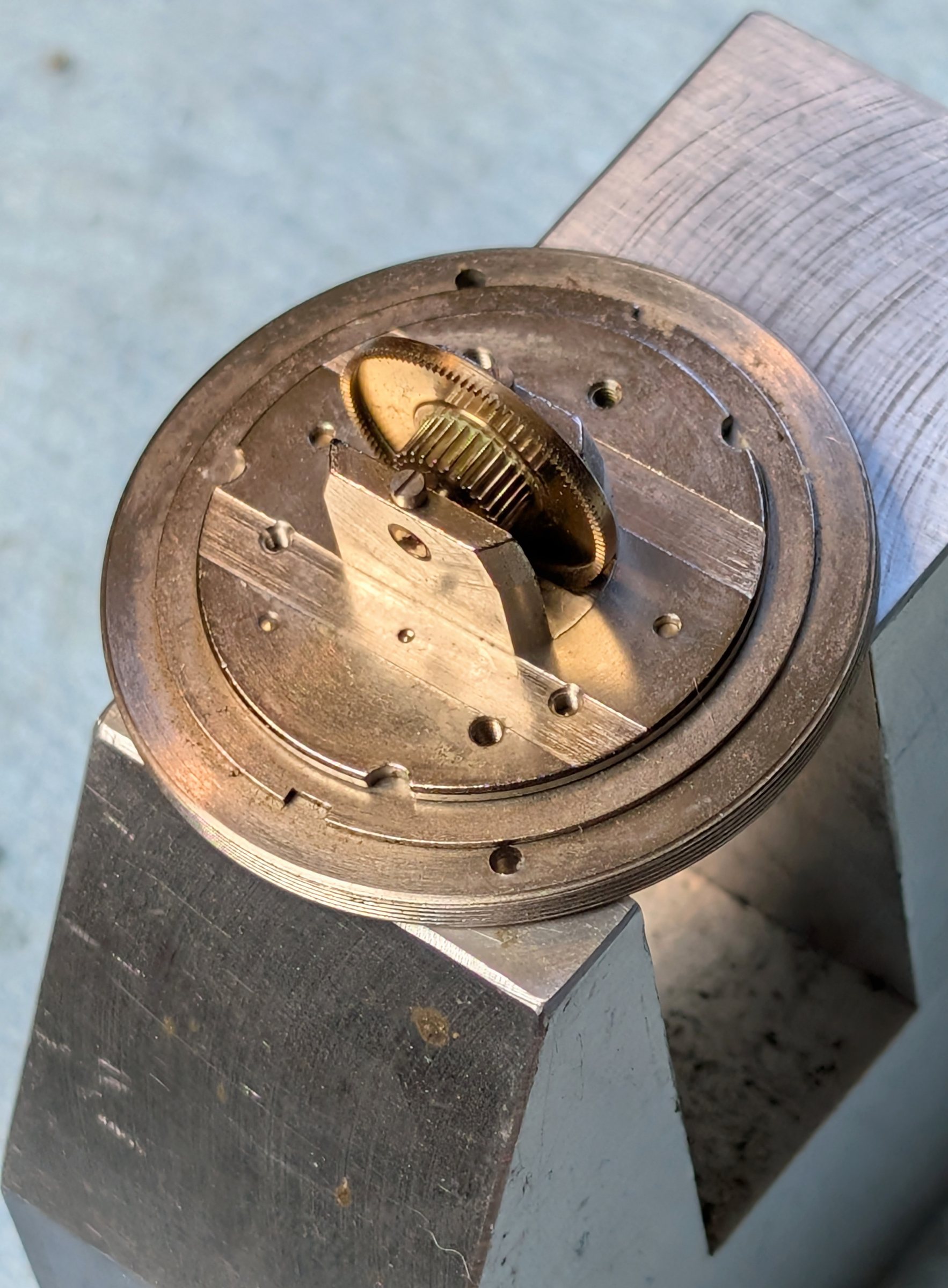
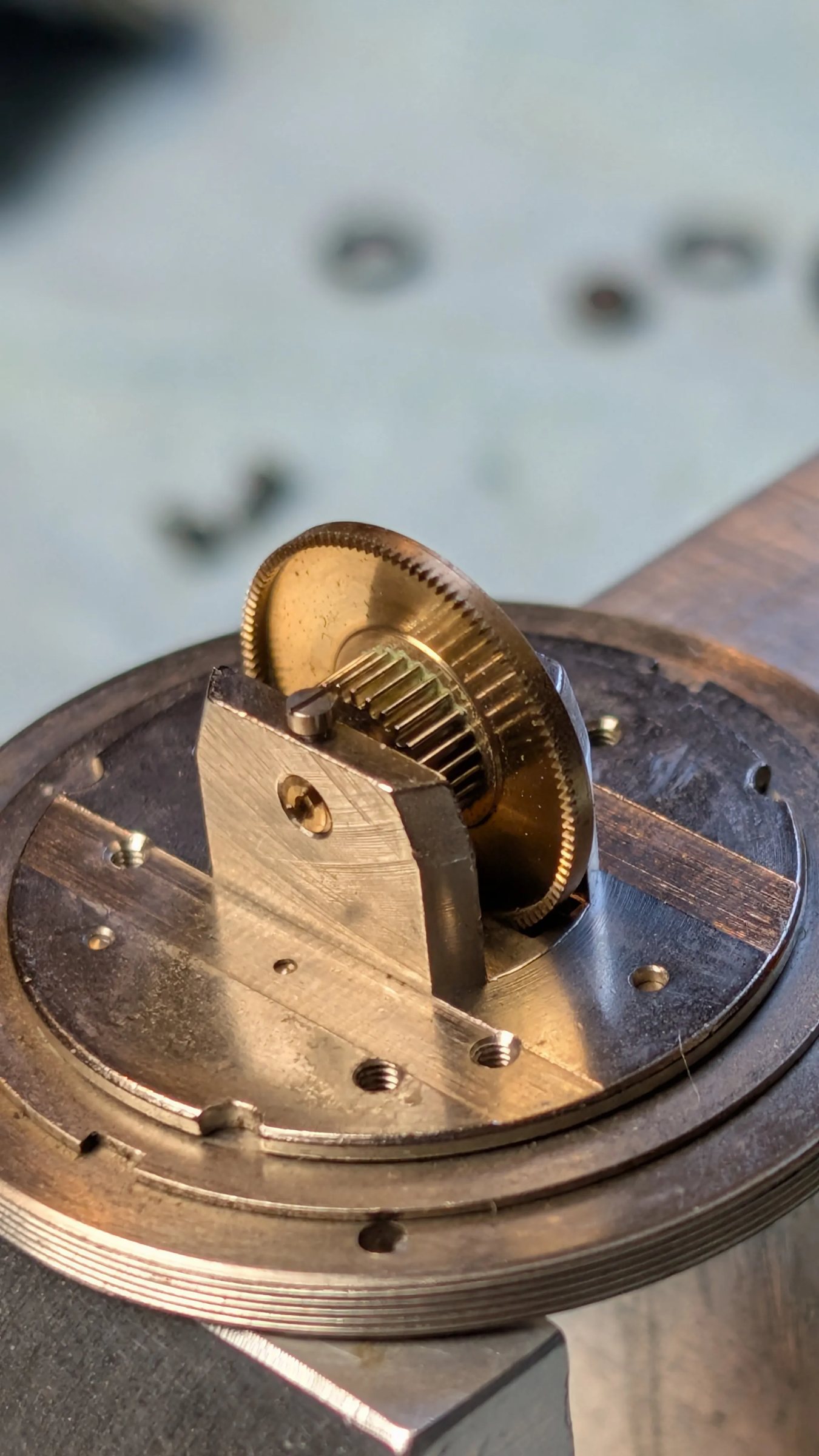
Meyer part numbers: crown gear [40]; bearing set screws [43]; bearings [44] — brass, each carrying a synthetic ruby jewel seated at its bottom. The gear runs on jeweled bearings, and the jewels are a documented failure point — see §07. Verified (Meyer, pp. 79–80)
Retaining bridge Verified
Flat steel bridge capturing the crown gear, secured by a single slotted screw, seated in a milled recess in the carrier plate.
Carrier plate Verified
Circular plate carrying the movement, with milled recesses for the bridge and threaded outer edge for the bezel.
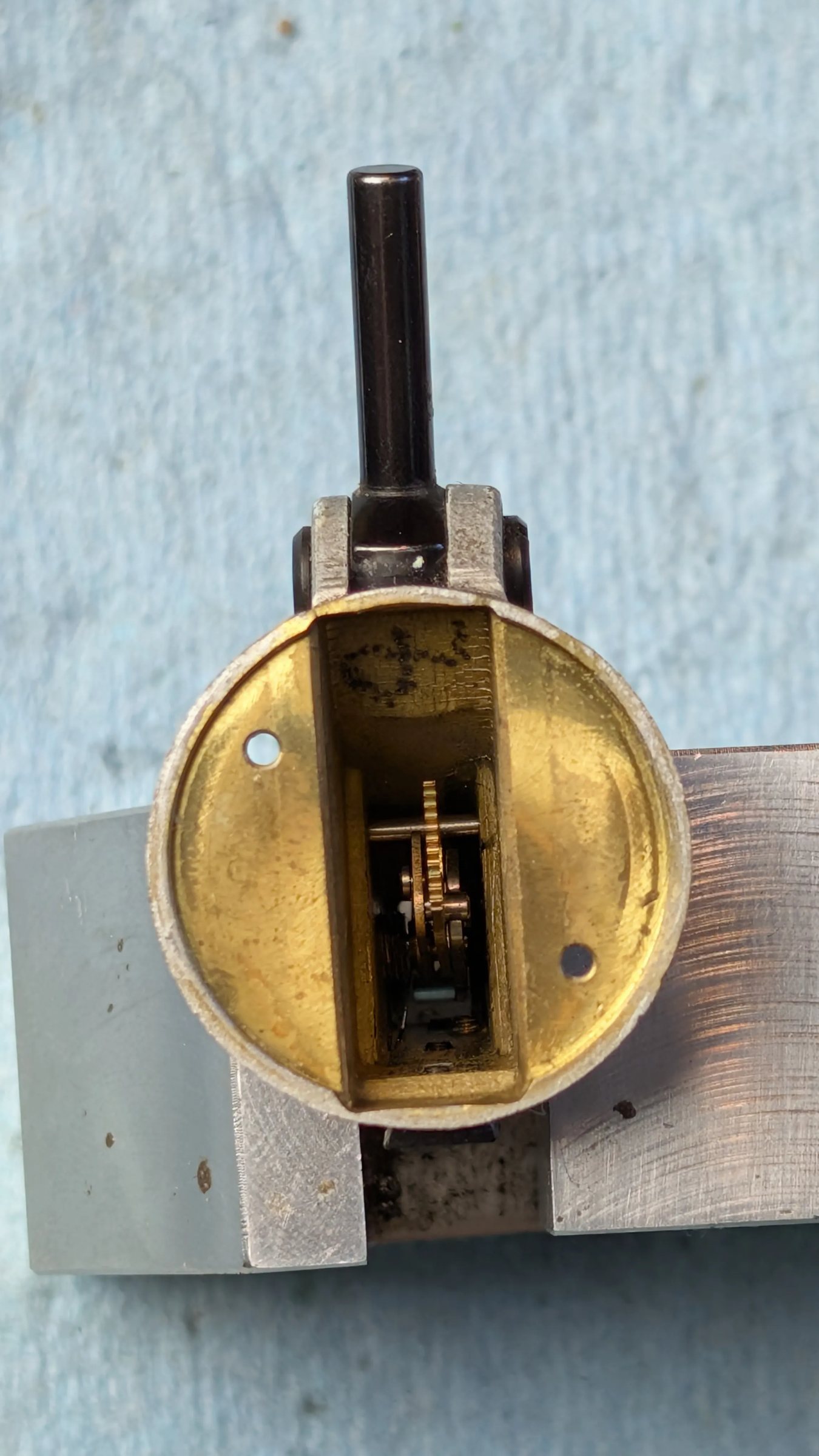
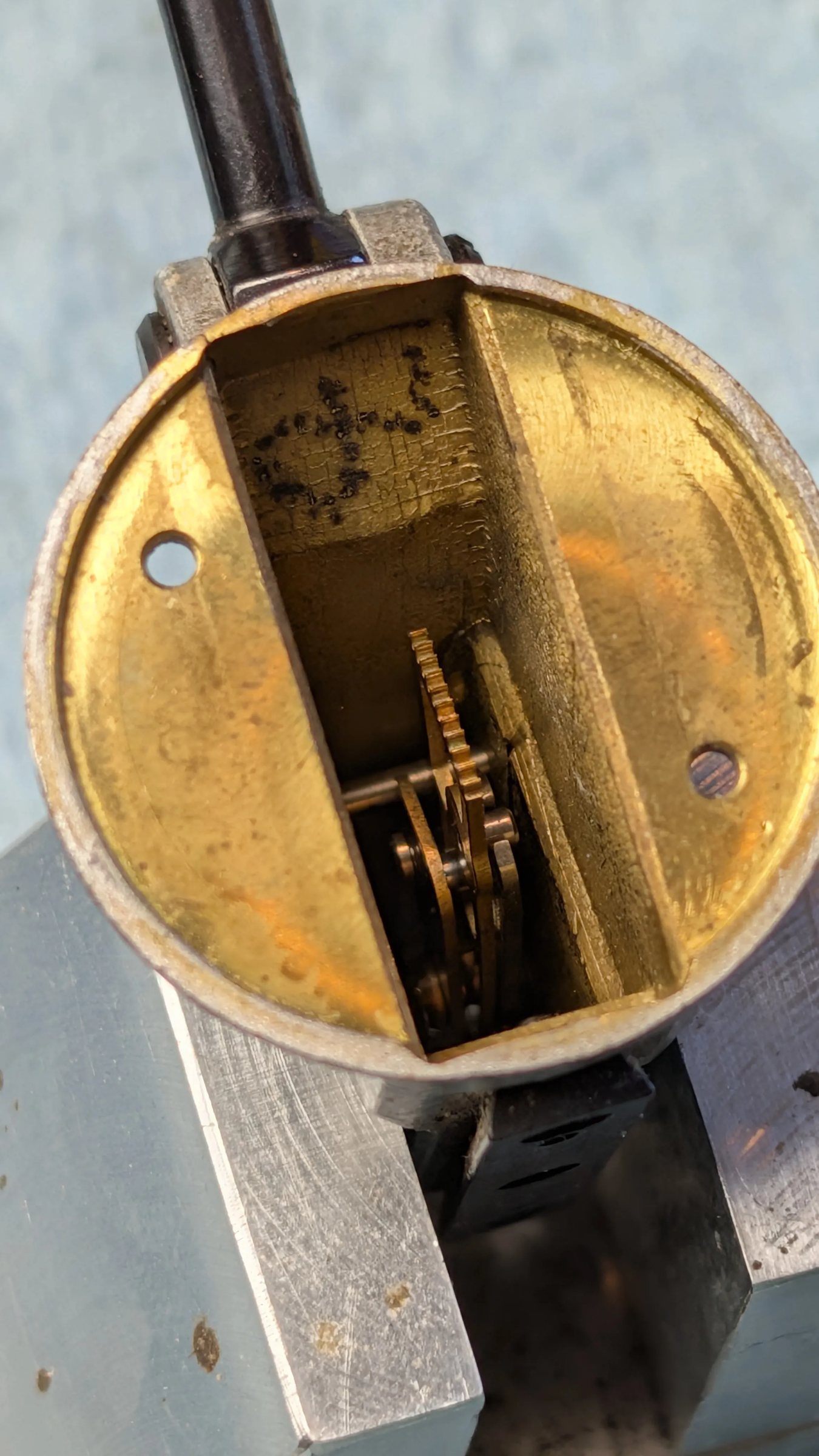
Body channel Verified
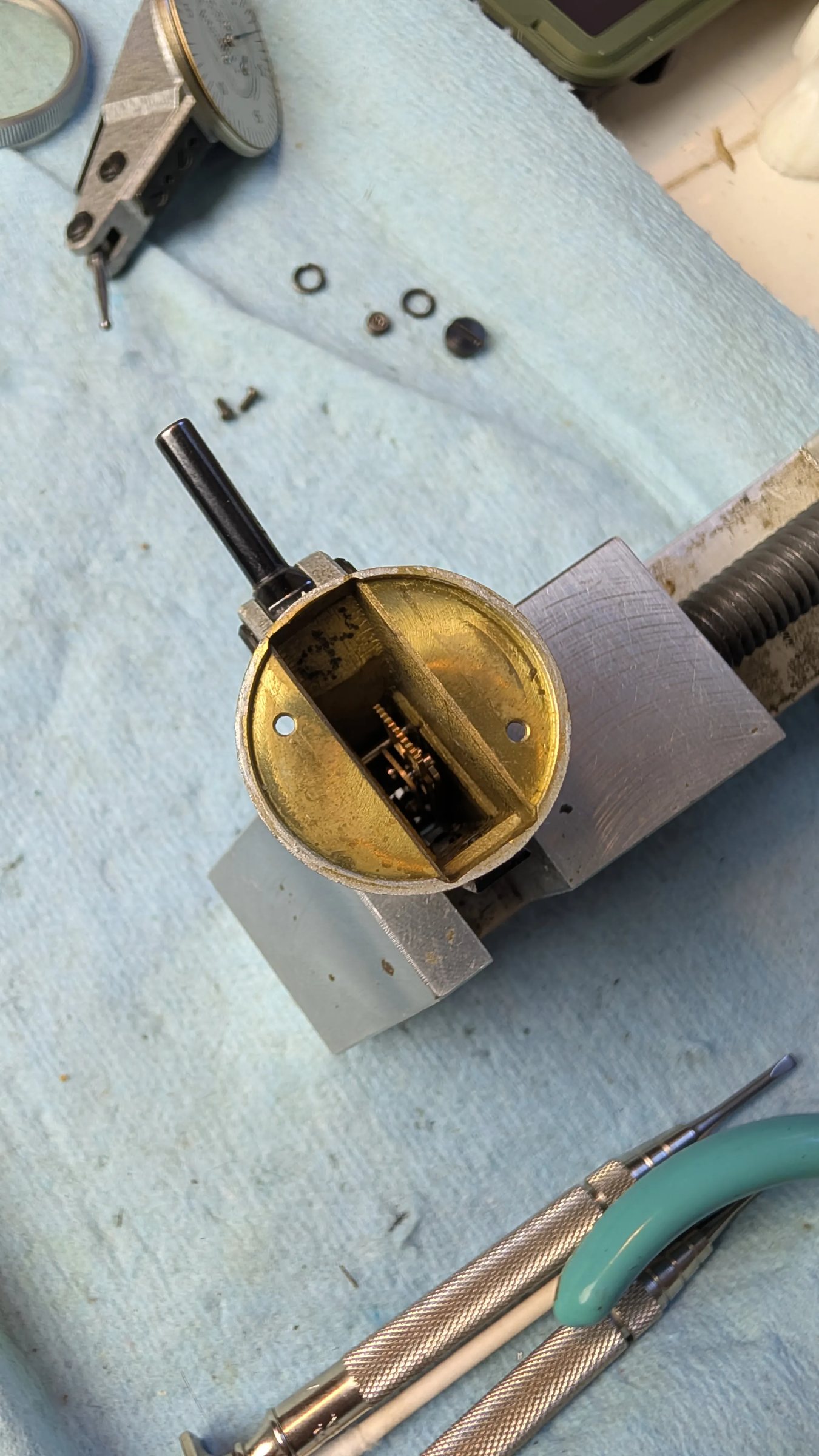
The movement is carried in a deep, narrow rectangular channel milled into the one-piece body. Neither the crown gear nor the lever mesh is reachable with the movement installed. This is the physical basis for the §06 requirement that preload be measured at the stylus rather than by driving internal components.
Internal lever assembly Verified
Attached to the stylus; drives the crown gear's peripheral teeth through the toothed end of the brass rack lever [8] — the rack is the physical interface at Mesh 1. Responsible for the movement's two-way action. Its mating position with the crown gear is a critical service adjustment — see §04.
Construction: three separate levers which engage one another. They are not captive to each other, and are handled as a set — held together with tweezers and introduced into the body of the indicator as a unit, in the same relative arrangement they must occupy when installed. Verified (Meyer, lever assembly plates)
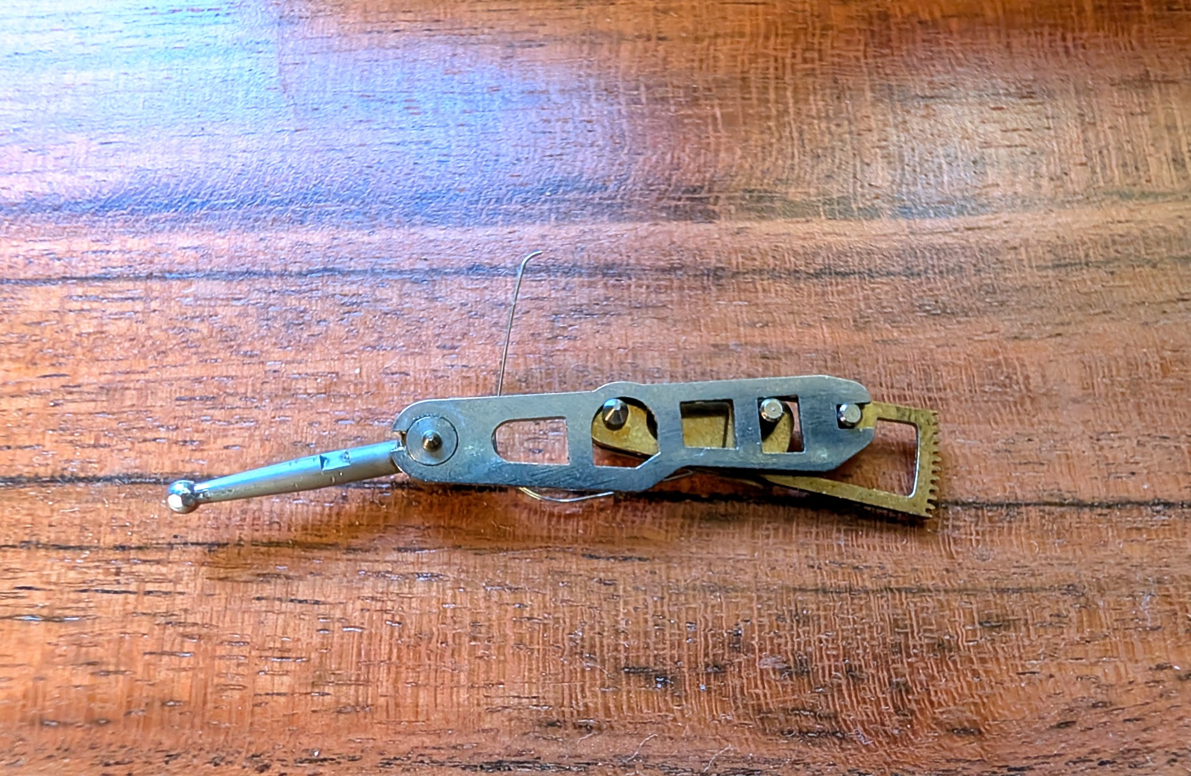
Unknown The criteria for verifying correct engagement. Meyer illustrates the correct state in the assembly plates; whether his diagnostic section states a verification test has not yet been checked. Not resolvable from in-body photography — the channel is too deep and the mating region falls in shadow. Requires observation with the assembly removed.
Pinion Verified
Driven by the crown gear's face set. Carries motion to the hairspring and the dial hand.
Hairspring Verified
Acts at the pinion — the high-speed, low-torque end of the train. Serves simultaneously as return spring and as the anti-backlash preload for the entire chain upstream of it.
Unknown Inner attachment construction: whether a discrete collet exists or the spring is fixed directly to the arbor. Determines whether inner-end correction is available. Not yet photographed.
Service parts — most frequently needed Verified
Meyer's shop reports the ten most-used spares, in his part numbering: crystals [25], contact point — .080″ carbide standard [12], stem attachment [20], ball bearing spanner nut [11], pivot [13], movement fastening screw [23], hairspring — .0005″ and .0001″ [42], rack lever for .0005″ models [8], dial screw [4], ball bearing [10]. (Meyer, Q&A)
Resale implication: this list is the harvest priority for donor units and the failure-rate ranking for triage. Note the hairspring's presence on it — springs needing replacement is routine, not exceptional, which supports fitting the correct spring over rehabilitating a doubtful one.
02 Mechanism — torque chain
Drive path: stylus displacement enters at the lever, crosses Mesh 1 into the crown gear's peripheral teeth, crosses Mesh 2 through 90° from the face teeth into the pinion, and arrives at the dial hand. Displacement is multiplied along this path; torque is divided.
Preload path: the hairspring sits at the far end, at the pinion. Its torque is reflected back upstream through both meshes. Because it acts at the low-torque end, its authority referred back to the stylus is multiplied by the train ratio — the spring has ample force. But the same ratio works against you for lash: play at Mesh 1 referred to the pointer is multiplied by the full ratio, so a small amount of play at the lever becomes a large visible dead band on the dial.
03 Preload — definitive
One physical state, three expressions with different datums. They do not interconvert.
| # | Expression | Datum | Property of |
|---|---|---|---|
| 1 | Turns wound in at assembly | wherever you started | the act |
| 2 | Angular deflection at rest | spring's free state | the spring |
| 3 | Residual torque at rest | absolute | the instrument |
Definition of record: preload is the deflection retained in the hairspring when the movement sits against its rest stop — the torque the spring exerts at zero stylus displacement. It is expressed as the deflection from the spring's free state — (2) — specified as the measuring force it produces at the stylus — (3) — and achieved by counted turns from an explicitly stated datum — (1).
Preload is one of two independent parameters
Spring torque across travel is
M(θ) = k · (θ₀ + θ)
where θ₀ is preload and k is the spring rate. Preload sets the intercept of the torque–displacement line; rate sets the slope. They are independent, and they fail differently — which makes them separable by measurement rather than by judgement.
| Measured behaviour | Parameter | Fault |
|---|---|---|
| Force low at rest, correct at full travel | θ₀ low | Preload insufficient. Correctable by adjustment. |
| Force correct at rest, falls short at full travel | k low | Spring rate wrong — fatigued or opened out. Not correctable by preload. |
| Force low at both | both low | Under-preloaded and degraded spring. |
Two-point measurement
- Measure measuring force at the stylus near the rest position.
- Measure again near full travel.
- Two points determine the line: the first gives the intercept, the difference across the two gives the slope.
Both readings are taken on the assembled instrument. This separates an adjustment problem from a spring-replacement problem without disassembly and without a reference unit.
Two constraints
- Floor, on the intercept. k·θ₀ referred upstream must exceed the torque required to hold every mesh against lash and friction. Below this, a dead band appears.
- Ceiling, on the whole line. k(θ₀ + θ) must remain within measuring force specification across the entire range — worst case at full travel. Above this, measuring force is excessive and wear accelerates.
The corresponding figure for the standard .0005″ models is not stated on that page and remains to be located or established — but the datum bounds it, gives the correct order of magnitude, and confirms that pre-wind is specified in fractions of a crown gear turn, exactly the expression-(1) form of §03 with the crown gear as the stated datum. Unknown
This adds a third failure mode to the table above: a spring whose k is wrong not through fatigue but because it was never the right spring. On any secondhand unit with an unexplained k fault, prior misrepair is a live hypothesis — and for resale stock, which is secondhand by definition, it should rank high. The two-point measurement detects it the same way; the remedy is the correct spring, not adjustment.
Unknown Factory measuring force figure. Not found in distributor literature. Obtain from a TESA datasheet or from Long Island Indicator. With that figure, the ceiling constraint becomes checkable absolutely on an assembled instrument with a gram gauge.
04 Fault — lever assembly mismating Verified
This is a mechanism fault, not a setup condition. Two-way action with no reversing lever is the defining characteristic of the movement, and it depends on correct lever-to-crown mating. No amount of preload adjustment will correct a mismated lever, and attempting to compensate with additional preload will only raise measuring force while leaving the fault in place.
Why this fault dominates. The lever assembly is three separate pieces that are not captive to one another (§01). Correct relationship between them is maintained only by holding them as a set during installation. Any disturbance during handling, insertion, or removal can shift one lever relative to the others, and nothing in the assembly resists it. A three-piece set that must be inserted into a deep body channel while held in alignment is inherently easy to disturb — which is consistent with this being the most frequently encountered fault in the line.
Signature: drive is transmitted in one direction of stylus travel and not the other. Distinguish carefully from a dead band, which is a delayed onset of return in a direction that otherwise works. These are different faults with different causes — see the fork in §05.
Unknown Verification criteria. Meyer shows the correctly engaged state photographically but does not state the test. Until this is recorded, §04 names a fault without a procedure to confirm or set it — see §11.
05 Primary fork
Sweep the stylus through full travel and characterise the loss.
| Observation | Reads as | Go to |
|---|---|---|
| Drive absent throughout one direction | Mechanism fault — lever mismating most likely | §04 |
| Returns in both directions, but onset is late — dead band before response | Uncompensated lash: insufficient retained preload, or play at a mesh | §06 |
| Returns, but force dies near the end of travel | Preload exhausted before end of range | §08 |
| Snags, jumps, or stops at a repeatable position; may catch and hold | Positional mechanical fault — bearing jewel or tooth damage at the crown gear | §07 |
06 Dead band — localisation
Run in this order. Each step is cheaper than the one after it.
Step 1 — Localise across Mesh 1
- Drive the movement from the lever and observe return onset.
- Drive from the crown gear and observe return onset.
- Compare.
| Result | Interpretation |
|---|---|
| Late from lever, clean from crown gear | Fault at or upstream of Mesh 1. Go to Step 2. |
| Late from both | Mesh 1 is sound. Preload quantity or Mesh 2 — go to Step 3. |
Step 2 — Mesh 1 inspection
- Inspect engagement depth of lever against peripheral teeth across the lever's full sweep. Look for any region riding shallow.
- Check the lever pivot for side shake. Play here appears at the stylus as dead band and is not correctable by preload.
- Confirm lever mating position per §04 even if operation is bidirectional — partial mismating may degrade engagement without fully losing a direction. Hypothesis
Step 3 — Quantify, then set preload
- Mount the indicator and run a reversal test: approach a pointer reading from one direction, then from the other, and record the difference. This is lost motion measured in the instrument's own units rather than felt by hand.
- Measure measuring force at the stylus with a gram gauge, at two points — near rest and near full travel — per §03. This yields both preload and spring rate, and establishes whether the fault is adjustable at all before you begin adjusting.
- Adjust preload a fraction of a turn at a time, re-measuring both figures each cycle.
- Stop at the first setting where reversal error falls to the instrument's resolution and measuring force is within specification.
- Verify the far end: confirm the spiral is not approaching coil-bind and torque has not run out at full travel.
- Record the turn count. It becomes the reference figure for the remainder of the batch.
Iteration cost: changing preload requires disassembly; measuring it requires assembly. Budget accordingly. The reversal figure indicates both direction and rough magnitude of the needed correction, so the loop converges rather than fishes.
07 Positional fault — snag, hang-up, jump Verified
Signature: the movement catches, jumps, or stops at a repeatable position; it may freeze temporarily and break loose. Distinct from a dead band (delayed onset everywhere) and from one-directional loss (§04). This is a hard interference, not a torque shortfall — additional preload masks it at the cost of measuring force, and fixes nothing.
Two documented causes, both at the crown gear. (Meyer, "Repairing a damaged crown gear", pp. 79–80)
Cause 1 — cracked or missing bearing jewel
Each brass crown gear bearing [44] carries a synthetic ruby jewel seated at its bottom. These jewels crack under stress, and a crack can be close to invisible. A cracked jewel produces exactly this fault class: the indicator hangs up, jumps at spots, or freezes intermittently. Meyer's rule: once the other possibilities have been checked, check the jewels.
- Quick test: wiggle the crown gear [40] in its bearings. Play means either the bearing set screw [43] is loose or the jewel is cracked or missing — a compromised jewel means replacing the bearing.
- Bearing service: loosen the set screw and push the offending bearing outward. Both bearings may need to come out to clear the crown gear for removal; before reassembly, inspect the gear itself for damage picked up while the bearing was failing.
Cause 2 — damaged crown gear teeth
Inspect the teeth under the loupe, concentrating on the angular position where the snag occurs. Broken pinions on the gear are not repairable — replace the gear.
Localisation procedure
- Drive the movement to the snag point and hold it there.
- Mark the crown gear's angular position at the snag.
- Inspect the teeth at that position under the loupe, and check both bearing jewels.
- If neither shows damage, sweep full travel and count snag recurrences — a defect recurring once per revolution of a given component identifies that component through the train ratio.
08 Preload retention — witness marks
Applicable when preload measures correct at rest but torque fails before end of travel, or when the dead band grows across repeated cycles.
Procedure
- Ink a fine witness line across the inner attachment, spanning onto the arbor.
- Ink a second across the outer end where it meets its anchor.
- Let dry. Cycle the movement through its working range twenty times.
- Examine both marks for registration.
Broken registration localises preload escape to that joint. Slip has a distinguishing signature: the dead band grows across cycles rather than staying constant.
09 Screen — magnetism
Run before mechanical adjustment on any hairspring complaint. Magnetised coils attract one another and to nearby steel, mimicking deformation and producing erratic torque.
- Detect: suspend a sewing needle on a thread near the movement, or use a compass.
- Correct: hold 2–3 cm above the demagnetiser pad, press and hold, sweep and flip through several orientations for 5–10 s, then withdraw to arm's length before releasing.
- Releasing while still close re-magnetises the work. This is the common error.
A shop containing magnetic bases has an ambient source.
10 Status register
- VerifiedCrown gear is compound, carrying peripheral and face tooth sets.
- VerifiedChain: stylus → lever → peripheral → crown → face → pinion → hairspring and hand.
- VerifiedNo angularity in the movement; crown form serves a 90° transfer.
- VerifiedHairspring acts at the pinion, serving as both return spring and anti-backlash preload.
- VerifiedLever mismating causes one-directional operation; most common fault in the line.
- VerifiedLever assembly is three separate, non-captive levers installed as a held set.
- HypothesisPartial lever mismating degrades engagement without fully losing a direction.
- HypothesisPlay at Mesh 1 is the leading candidate for a dead band that clears when driven from the crown gear.
- UnknownFactory measuring force figure for the 312B-1V.
- UnknownHairspring inner attachment construction — discrete collet or fixed to arbor.
- UnknownFace and peripheral tooth counts; train ratio.
- UnknownLever assembly internal construction — not yet accessible for observation.
11 Open questions
- Complete the reconciliation with Meyer's diagnostic section. His governing principle is now captured in §00, but the remainder of that section has not been read against §04–§08. Check in particular whether he treats positional snags, lever mating verification, or preload — §03 is entirely uncorroborated reasoning and he may contradict it.
- Document the lever assembly out of the body, and establish the criteria for verifying correct mating — §04 currently names a fault with no procedure attached to confirm or set it.
- Photograph the hairspring inner attachment down the arbor axis. Resolves whether inner-end correction is available.
- Face teeth square-on for tooth count; establish train ratio.
- Obtain factory measuring force figure.
- Vertical-model photography pass, including a 312B-1V, to complete §01–§02 coverage across the family. Deferred until such a unit is next on the bench.
- Establish preload turn count empirically and record per model variant.
12 Sources
- Horizontal-model Interapid, disassembled — photographic source for §01 and §02.
- 312B-1V, vertical model — subject instrument for the fault worked in §05–§08. Photography pending.
- Field observation across multiple Interapid repairs — §04.
- Meyer, René Urs, Interapid Indicator Repair Manual — disassembly, cleaning, reassembly, adjustment, and diagnosis; source for the three-lever construction and installation method in §01. Illustrations and text are cited, not reproduced. Meyer's diagnostic section is not yet reconciled with this document — see §11.
- Long Island Indicator Service — Meyer's shop; channel for factory-level figures.