Calibration
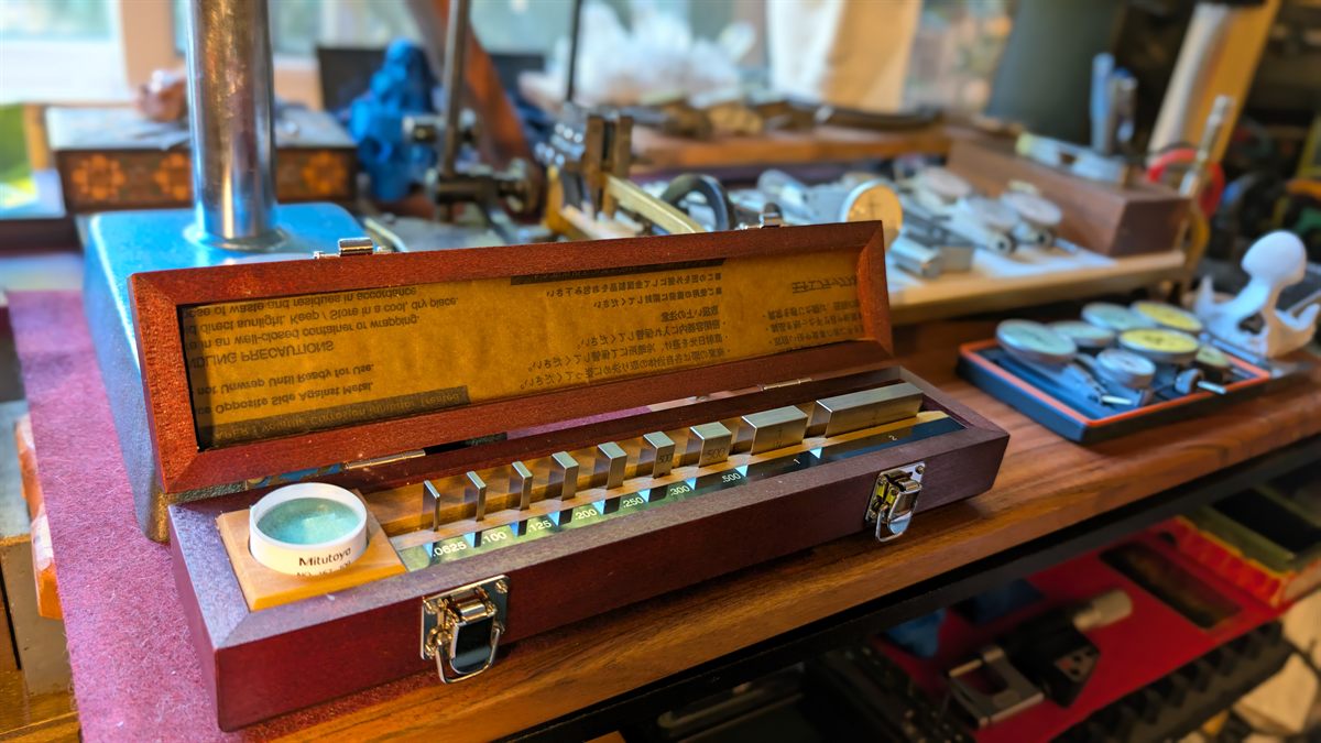
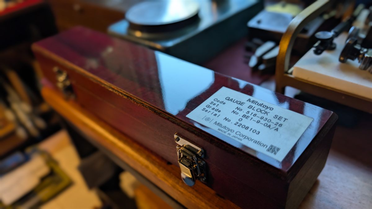
Accuracy verified at multiple positions throughout the full travel range of the device. Every indicator is read on the bench's calibration rig, and the rig is checked against a grade 0 gage block set calibrated by an accredited laboratory — standards traceable to NIST.
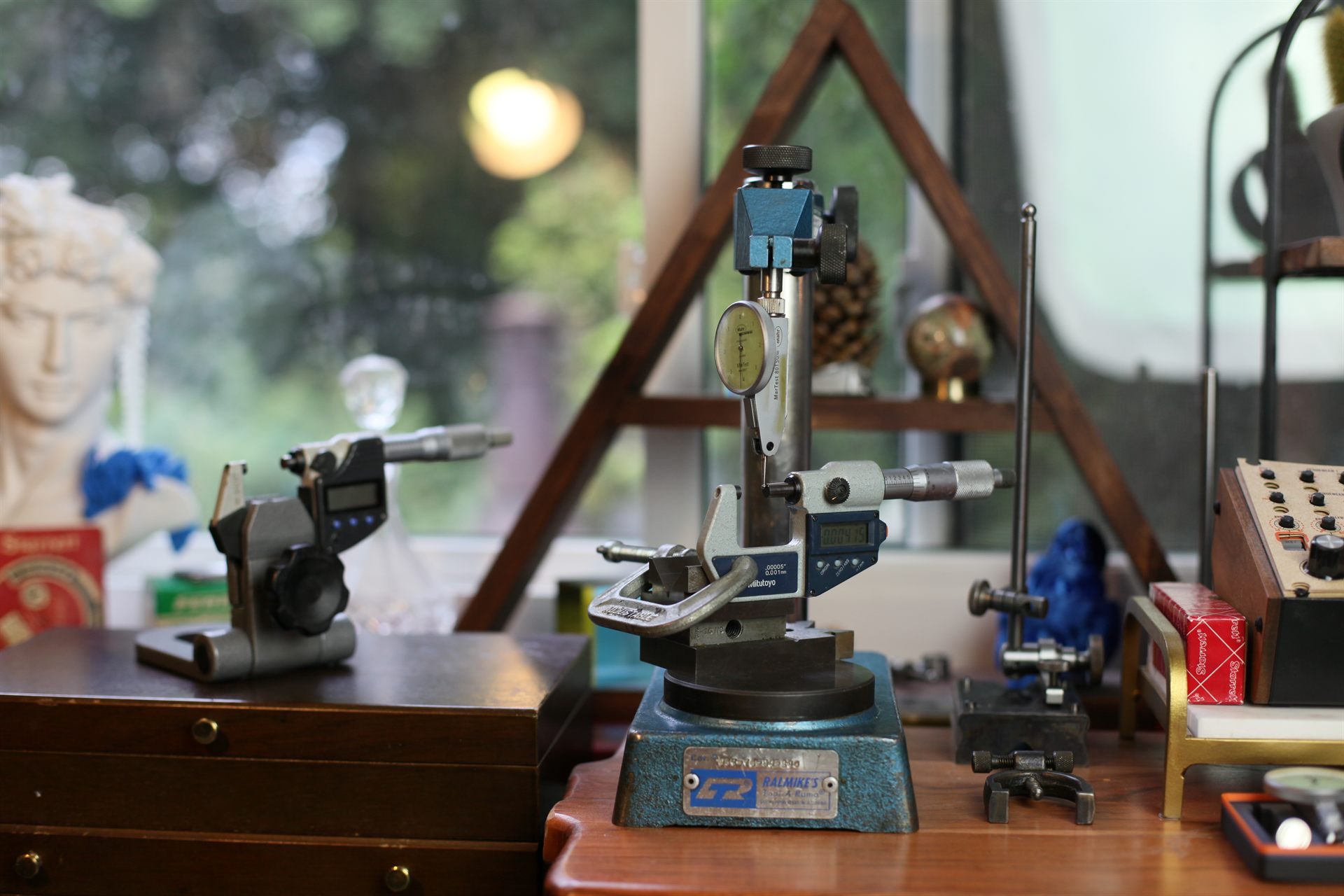
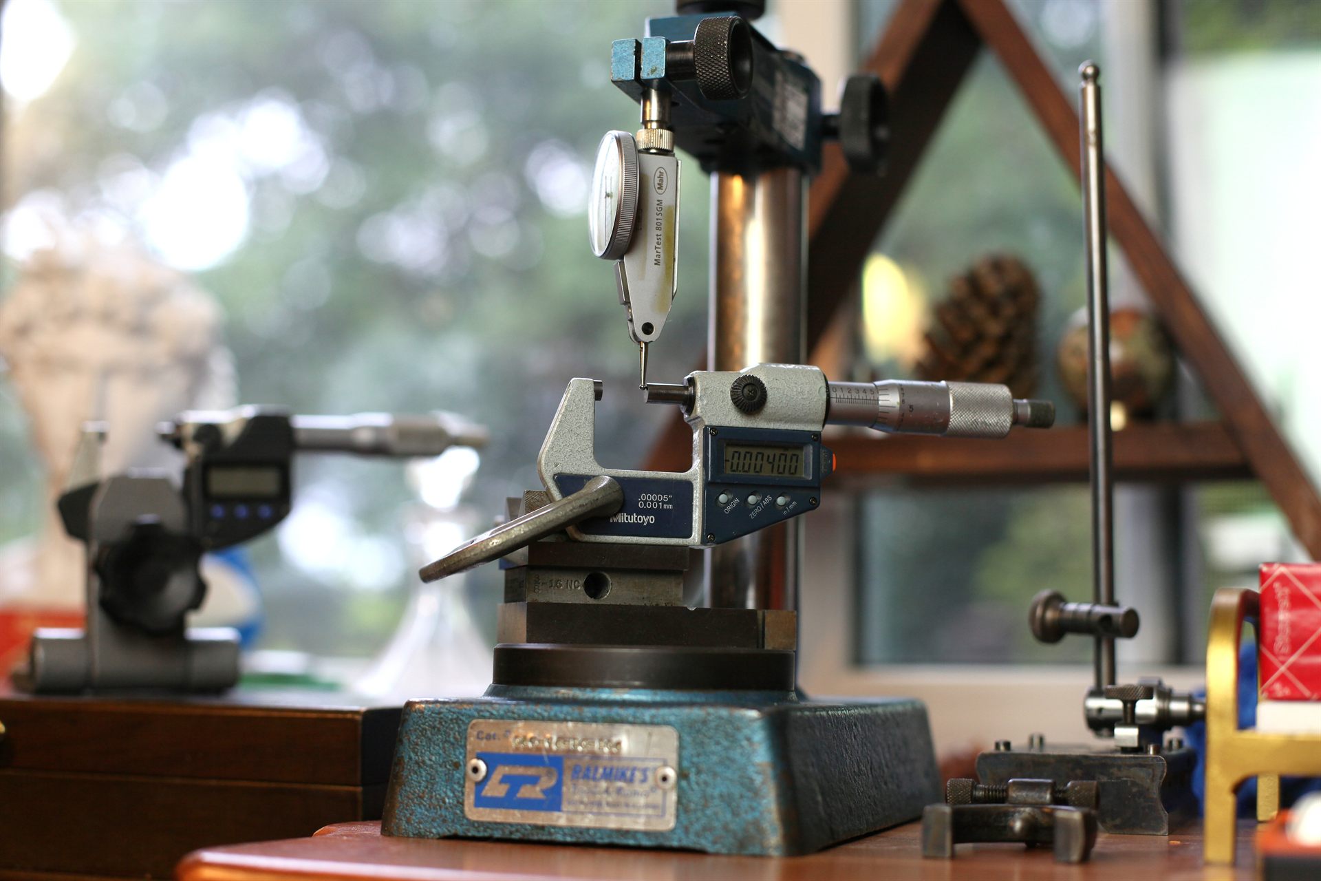
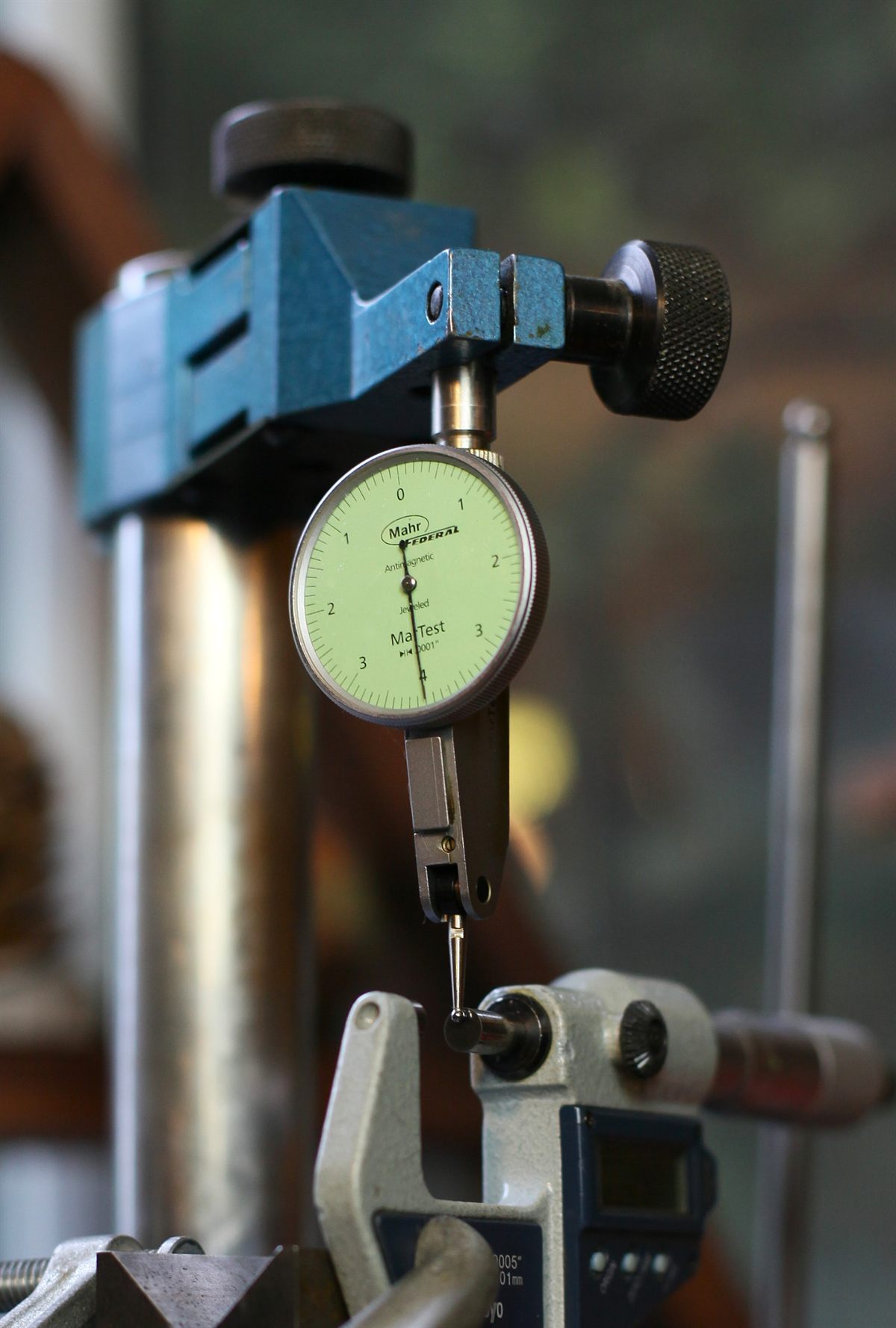
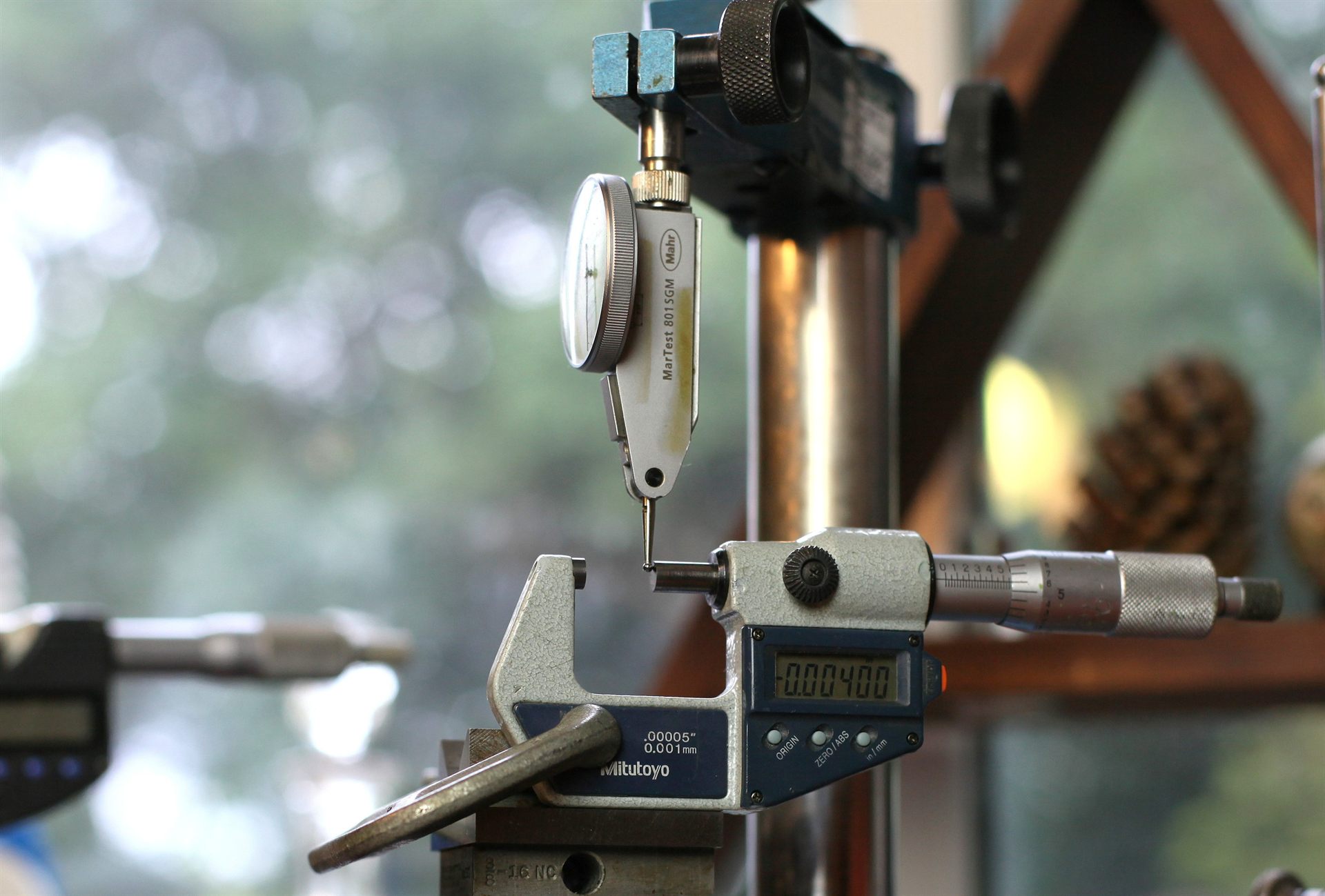
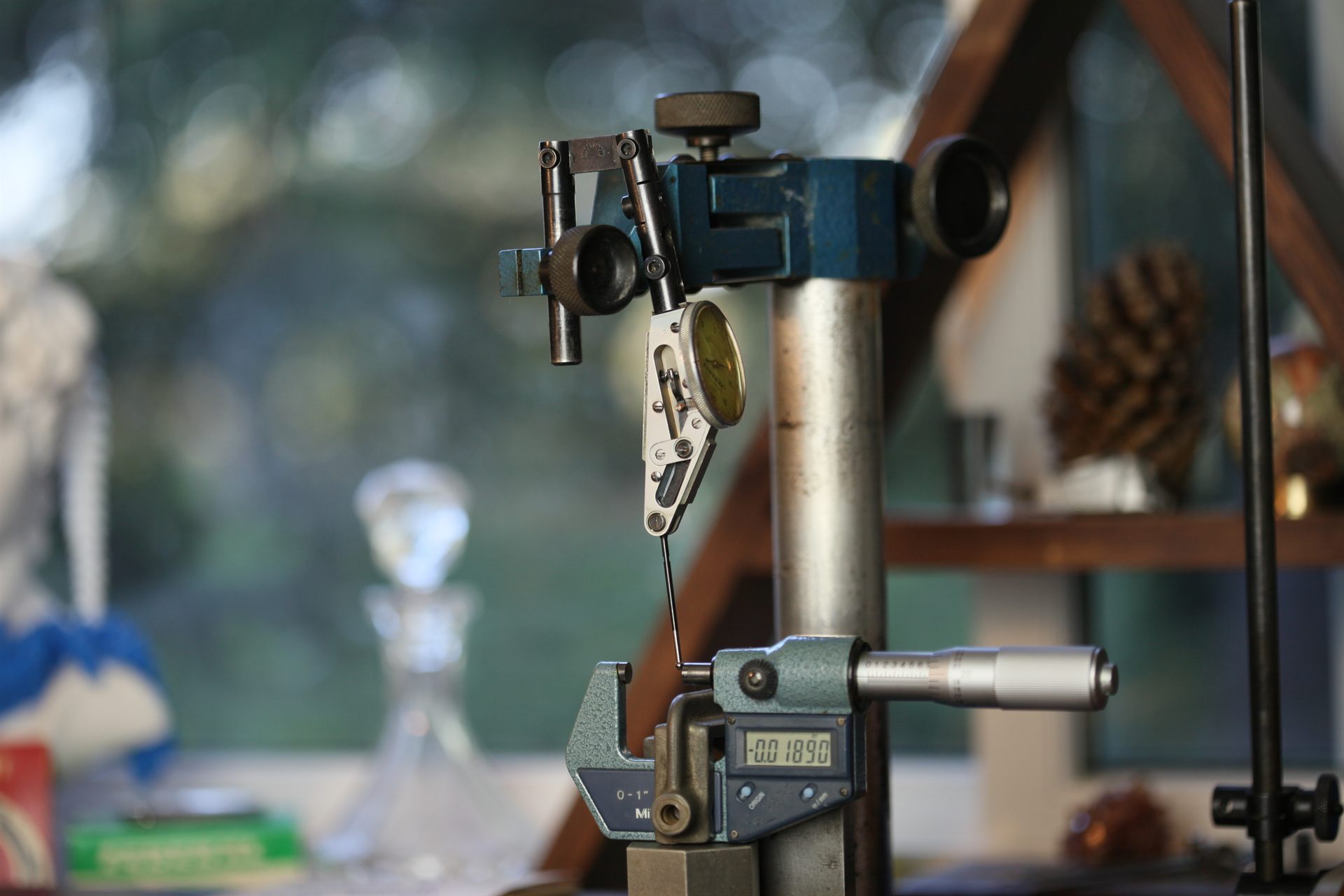
Every instrument that leaves this bench gets this check, without exception. It is not an accredited calibration and no certificate is issued; if your quality system requires an ISO/IEC 17025 certificate, you need an accredited lab, and any cert I can provide won't survive your auditor. A data-bearing accuracy report is coming as a separate service.
The reference set is a micrometer inspection set: ten blocks, not the usual run of sizes but a deliberate sequence — 0.105, 0.210, 0.315, 0.420, 0.500, 0.605, 0.710, 0.815, 0.920 and 1.000 inch. Each step of 0.105 inch is four full turns of the spindle and a fifth of a turn more, so every block in the sequence brings the spindle to rest at a different point of its rotation, a fifth of a turn round from the last. Five of them carry it through a whole revolution. A worn or unevenly cut thread reads true at some angles and not at others; a set that only landed on whole turns would never see it. The half-inch and the inch land on whole turns and check the ends of the travel, and the optical flat and parallel that ride with the set check that the measuring faces are flat and parallel to each other. Grade 0, under ISO 3650 and ASME B89.1.9 alike, holds each block to within 0.14 micrometre of its marked length up to 25 millimetres and 0.20 at the inch — five to eight millionths of an inch — and to no more than 0.10 micrometre of variation across its measuring face.